Structure for control register bit parsing. More...
Public Attributes | |
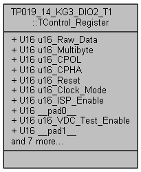
| U16 | u16_Raw_Data |
| Control register raw data. More... | |
| struct { | |
| U16 u16_Multibyte:1 | |
| Bit 0 - Multibyte flag, controls chip select for multibyte transfer. More... | |
| U16 u16_CPOL:1 | |
| Bit 1 - Clock polarity bit. More... | |
| U16 u16_CPHA:1 | |
| Bit 2 - Clock phase bit. More... | |
| U16 u16_Reset:1 | |
| Bit 3 - DUT reset bit: 0 - Normal operation, 1 - Reset condition. More... | |
| U16 u16_Clock_Mode:2 | |
| Bit 4..5 - DUT clock enable bit: 0 - Clock generation disabled, 1 - Clock generation enabled, 2 - Clock tied low, 3 - Clock tied high. More... | |
| U16 u16_ISP_Enable:1 | |
| Bit 6 - ISP protocol enable for FPGA: 0 - Disable, 1 - Enable. More... | |
| U16 __pad0__:1 | |
| Bit 7 - Reserved. More... | |
| U16 u16_VDC_Test_Enable:1 | |
| Bit 8 - Test mode enable: 0 - Disable, 1 - Enable. More... | |
| U16 __pad1__:1 | |
| Bit 9 - Reserved. More... | |
| U16 __pad2__:1 | |
| Bit 10 - Reserved. More... | |
| U16 __pad3__:1 | |
| Bit 11 - Reserved. More... | |
| U16 __pad4__:1 | |
| Bit 12 - Reserved. More... | |
| U16 u16_Red_Led_Enable:1 | |
| Bit 13 - Mode for red led: 0 - Disable, 1 - Enable. More... | |
| U16 u16_Green_Led_Enable:1 | |
| Bit 14 - Mode for green led: 0 - Disable, 1 - Enable. More... | |
| U16 u16_Yellow_Led_Enable:1 | |
| Bit 15 - Mode for yellow led: 0 - Disable, 1 - Enable. More... | |
| }; | |
| Control register bit parsing structure. More... | |
Detailed Description
Structure for control register bit parsing.
Member Data Documentation
◆
| struct { ... } |
Control register bit parsing structure.
◆ __pad0__
| U16 TP019_14_KG3_DIO2_T1::TControl_Register::__pad0__ |
Bit 7 - Reserved.
◆ __pad1__
| U16 TP019_14_KG3_DIO2_T1::TControl_Register::__pad1__ |
Bit 9 - Reserved.
◆ __pad2__
| U16 TP019_14_KG3_DIO2_T1::TControl_Register::__pad2__ |
Bit 10 - Reserved.
◆ __pad3__
| U16 TP019_14_KG3_DIO2_T1::TControl_Register::__pad3__ |
Bit 11 - Reserved.
◆ __pad4__
| U16 TP019_14_KG3_DIO2_T1::TControl_Register::__pad4__ |
Bit 12 - Reserved.
◆ u16_Clock_Mode
| U16 TP019_14_KG3_DIO2_T1::TControl_Register::u16_Clock_Mode |
Bit 4..5 - DUT clock enable bit: 0 - Clock generation disabled, 1 - Clock generation enabled, 2 - Clock tied low, 3 - Clock tied high.
Referenced by TP019_14_KG3_DIO2_T1::Chip_Connect().
◆ u16_CPHA
| U16 TP019_14_KG3_DIO2_T1::TControl_Register::u16_CPHA |
Bit 2 - Clock phase bit.
Referenced by TP019_14_KG3_DIO2_T1::Chip_Connect().
◆ u16_CPOL
| U16 TP019_14_KG3_DIO2_T1::TControl_Register::u16_CPOL |
Bit 1 - Clock polarity bit.
Referenced by TP019_14_KG3_DIO2_T1::Chip_Connect().
◆ u16_Green_Led_Enable
| U16 TP019_14_KG3_DIO2_T1::TControl_Register::u16_Green_Led_Enable |
Bit 14 - Mode for green led: 0 - Disable, 1 - Enable.
◆ u16_ISP_Enable
| U16 TP019_14_KG3_DIO2_T1::TControl_Register::u16_ISP_Enable |
Bit 6 - ISP protocol enable for FPGA: 0 - Disable, 1 - Enable.
Referenced by TP019_14_KG3_DIO2_T1::Chip_Connect().
◆ u16_Multibyte
| U16 TP019_14_KG3_DIO2_T1::TControl_Register::u16_Multibyte |
Bit 0 - Multibyte flag, controls chip select for multibyte transfer.
◆ u16_Raw_Data
| U16 TP019_14_KG3_DIO2_T1::TControl_Register::u16_Raw_Data |
Control register raw data.
Referenced by TP019_14_KG3_DIO2_T1::Chip_Connect(), TP019_14_KG3_DIO2_T1::Chip_Disconnect(), TP019_14_KG3_DIO2_T1::Chip_Reset(), and TP019_14_KG3_DIO2_T1::Execute().
◆ u16_Red_Led_Enable
| U16 TP019_14_KG3_DIO2_T1::TControl_Register::u16_Red_Led_Enable |
Bit 13 - Mode for red led: 0 - Disable, 1 - Enable.
◆ u16_Reset
| U16 TP019_14_KG3_DIO2_T1::TControl_Register::u16_Reset |
Bit 3 - DUT reset bit: 0 - Normal operation, 1 - Reset condition.
Referenced by TP019_14_KG3_DIO2_T1::Chip_Connect(), TP019_14_KG3_DIO2_T1::Chip_Disconnect(), and TP019_14_KG3_DIO2_T1::Chip_Reset().
◆ u16_VDC_Test_Enable
| U16 TP019_14_KG3_DIO2_T1::TControl_Register::u16_VDC_Test_Enable |
Bit 8 - Test mode enable: 0 - Disable, 1 - Enable.
Referenced by TP019_14_KG3_DIO2_T1::Execute().
◆ u16_Yellow_Led_Enable
| U16 TP019_14_KG3_DIO2_T1::TControl_Register::u16_Yellow_Led_Enable |
Bit 15 - Mode for yellow led: 0 - Disable, 1 - Enable.
The documentation for this union was generated from the following file:
- ConOpSys/Hardware/P019_14_KG3_DIO2/P019_14_KG3_DIO2.h